
🔧 PumpLocked Platform
Displacement Pump Teardown & Rebuild Instructions
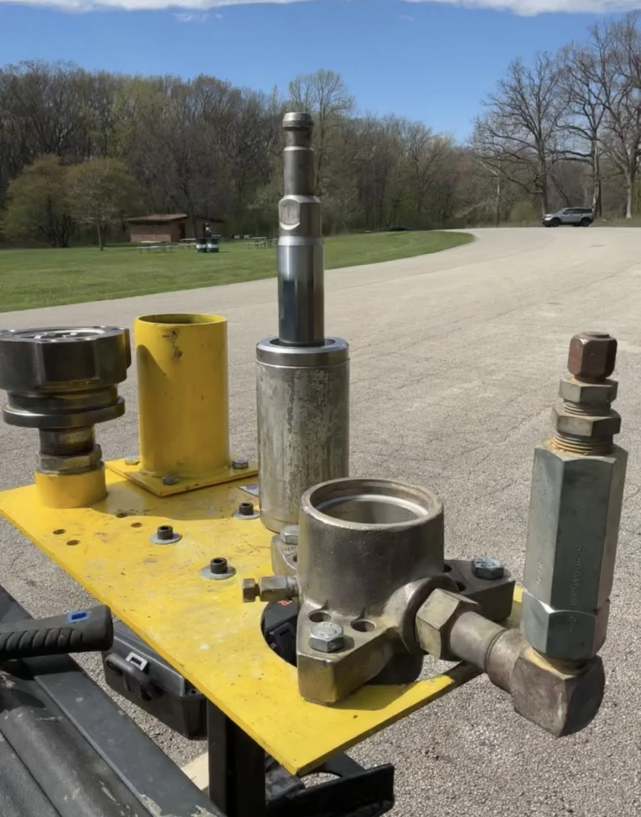
(1800 pump shown using PLP-1800 adapter on 2400 platform)
Overview
This guide demonstrates the steps to complete the teardown and rebuild of a displacement pump using the PumpLocked Platform. The PumpLocked Platform secures the pump in a single vertical working position, upside down, throughout the entire rebuild process, eliminating the need for a table vise, a hydraulic press, or multiple technicians. This method provides improved control, organization, safety, and accuracy across all high-torque, seal-critical operations.
The steps below are a good pattern to follow and learn from until the rebuild method with the platform and its benefits are well understood. Once you have accomplished this, it will be apparent that after step 2, you can essentially develop your own sequence that best suits your operating style.
Looking for a simpler overview of the Graco 1800 rebuild setup? View the Graco 1800 Pump Rebuild page.
Step1
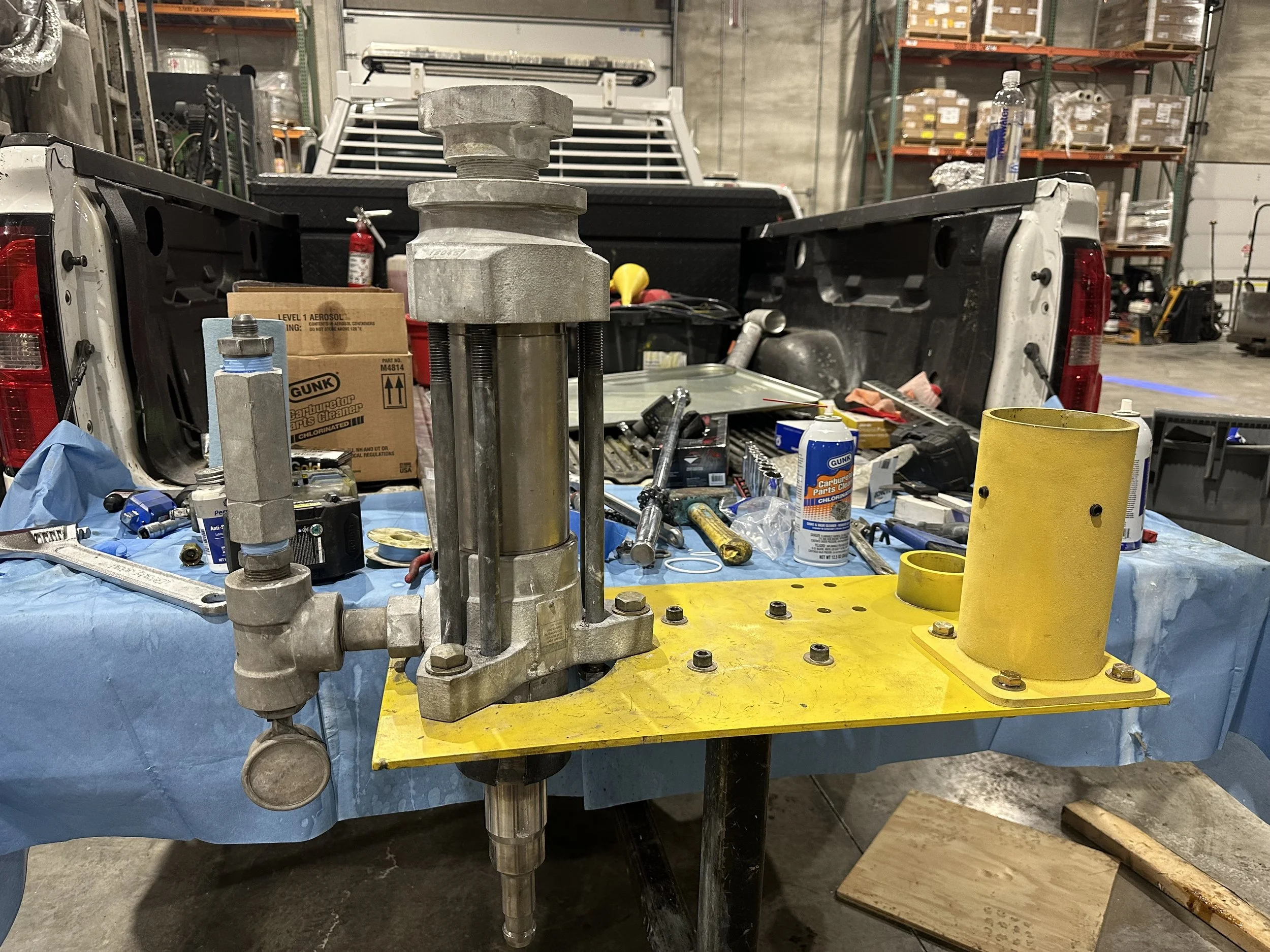
Turning the pump upside down and placing it on the left side of the platform, aligning the three bolt holes of the pump with the platform's holes while keeping the check valve of the pump on the left side of the platform.
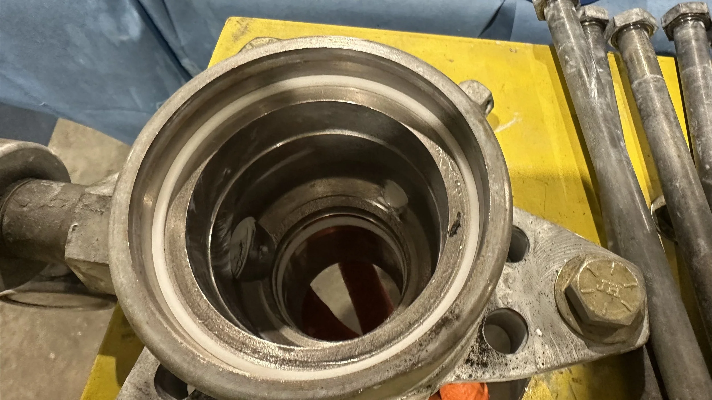
Step2
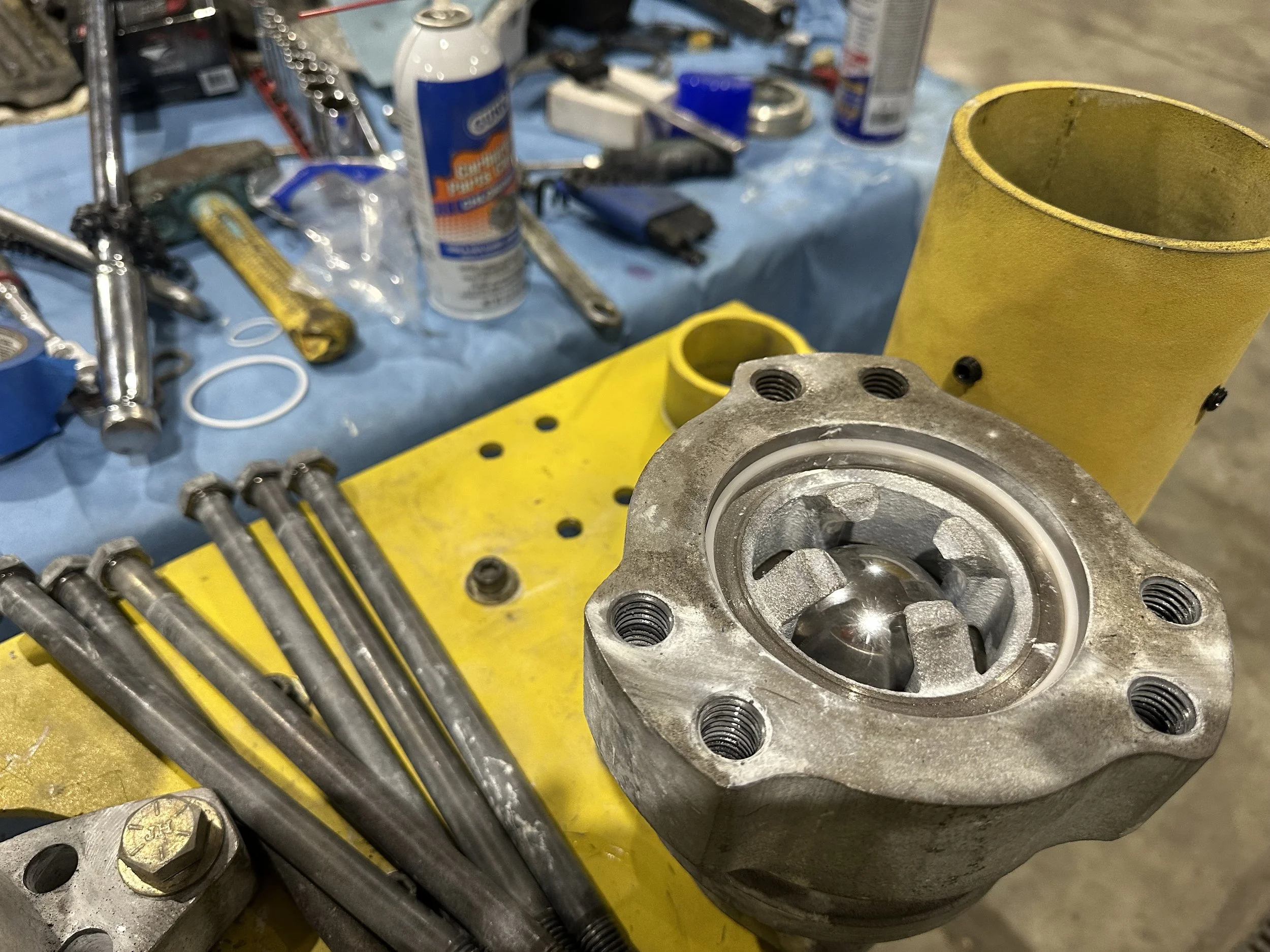
Undo the 6- 12” tie bolts that hold the lower and upper housing, and pull the lower, holding the components with thumbs as it is turned over. Take the lower and lock it into place on the right side of the platform, either with the male cam or flange, whichever your pump has. Begin cleaning out components, and keep the large bearing ball available for a later step.
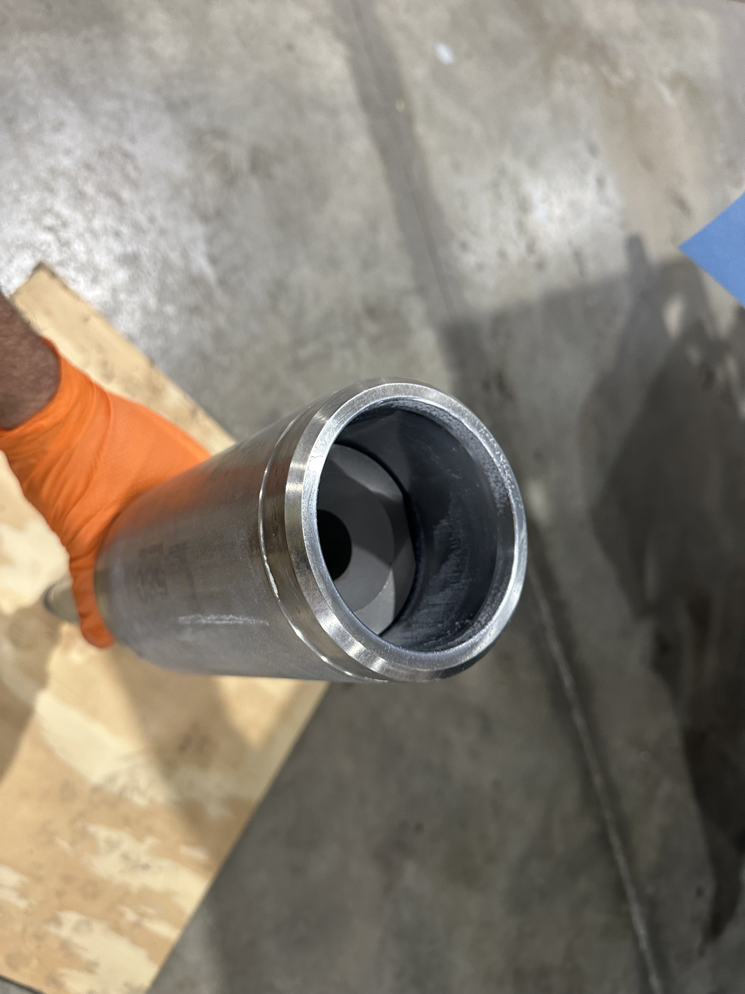
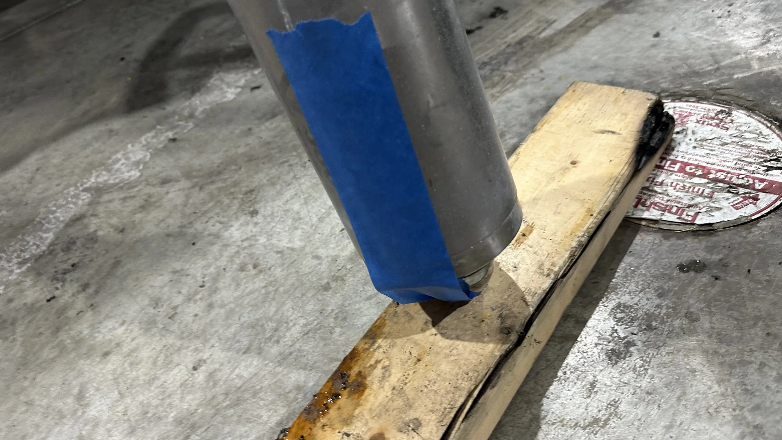
Step3
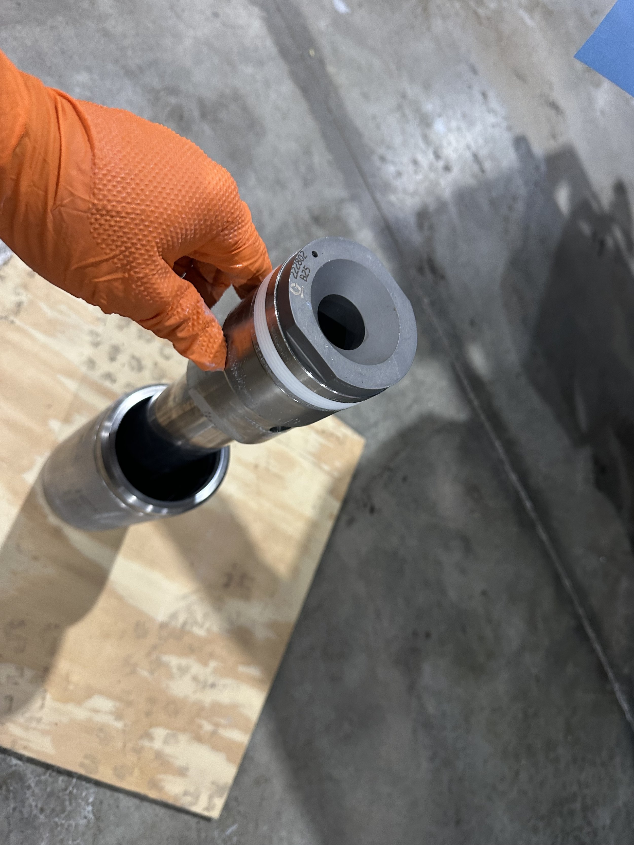
Pull the cylinder with the piston from the top housing. Place over the waste bin and allow any residual material to drip out, and clean as much as possible. Once cleaned, place the top centering ring either 1800 or 2400, depending on the pump you are working with. While holding the cylinder and top centering ring in place, turn the cylinder over and tap the end of the shaft against a 2x4 wooden block until the piston is extracted.
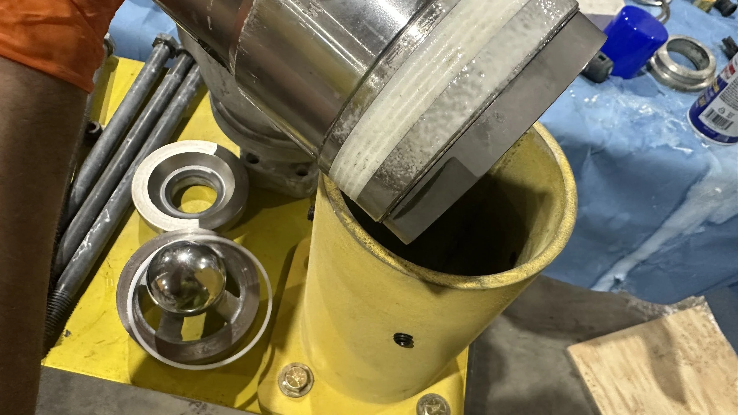
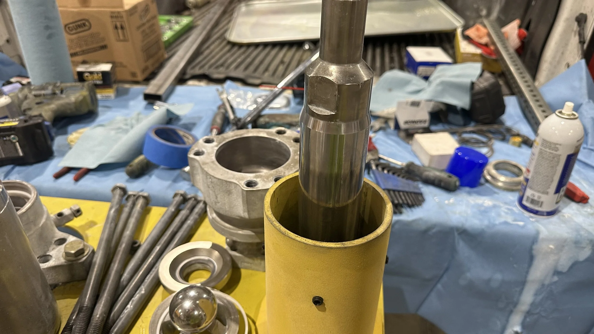
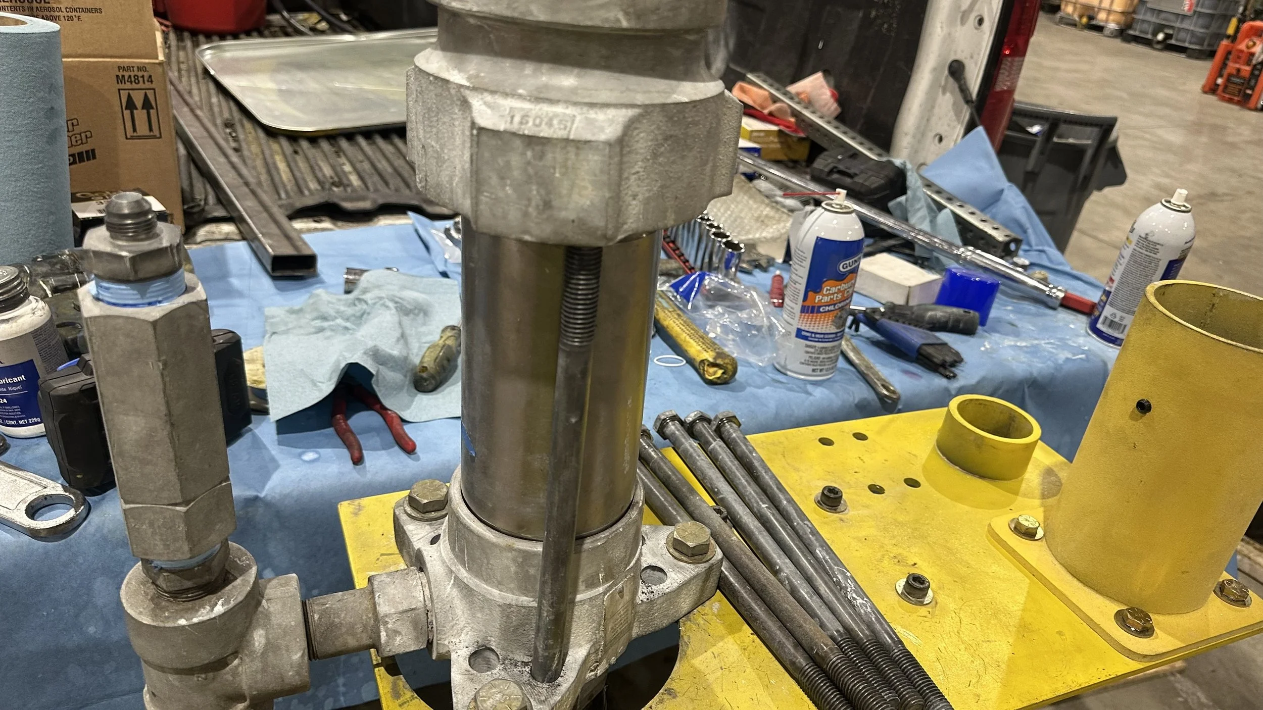
Step4
Insert piston lower into platform tower noting the two opposing flats and align and lock into position with the tower’s two opposing flats for the 2400 or using the 1800 reduction adapter if you are working with the 1800. (The adapter lower is for locking into the towers platform with the 2400 sizing while the top of the adapter is set to accomodate the 1800 sized piston lower body).
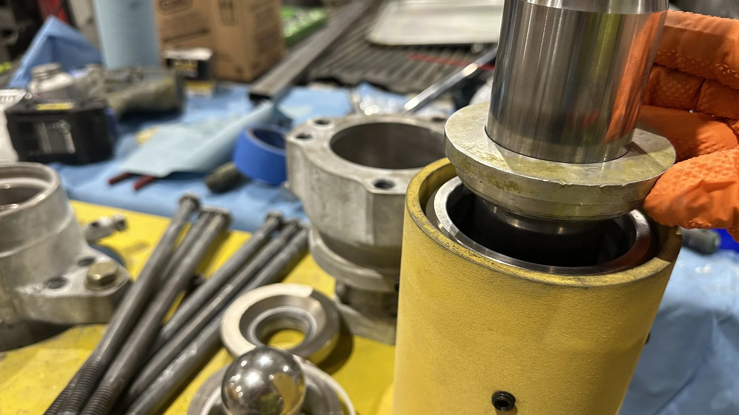
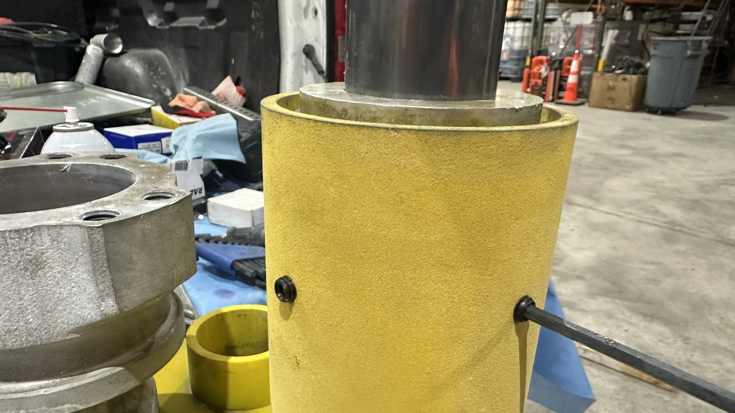
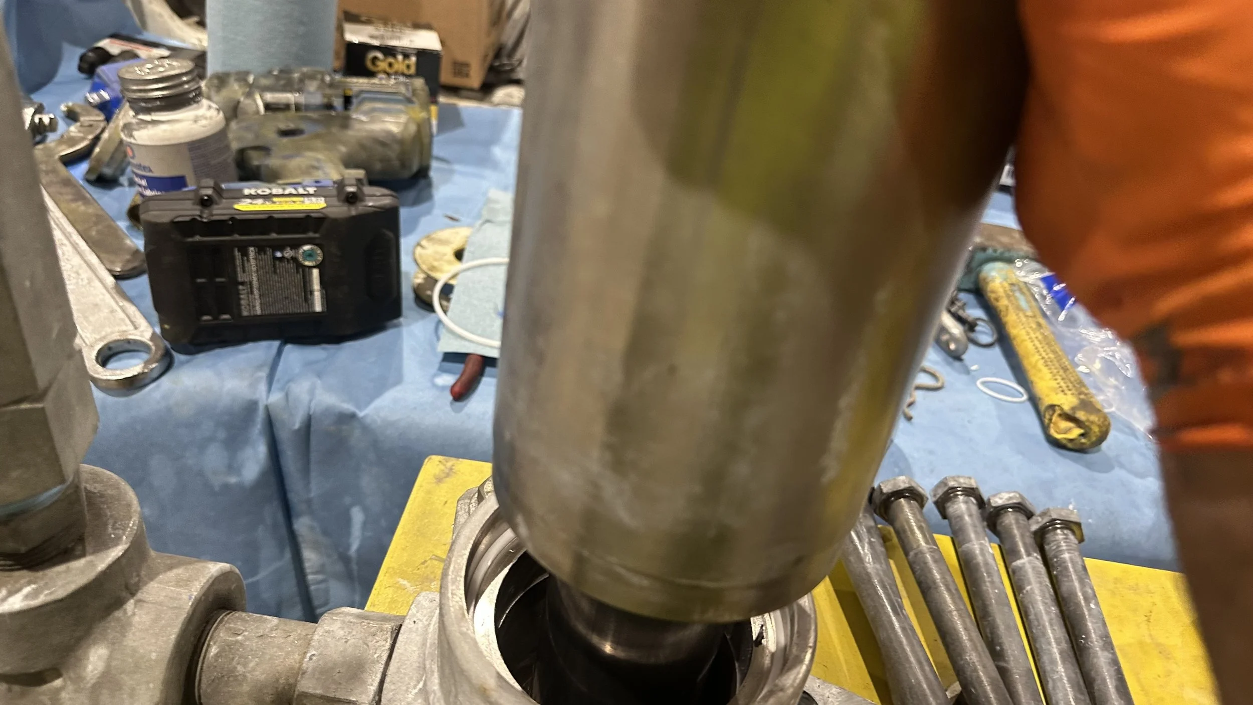
Step5
With piston locked into position insert the pump cylinder and the top centering ring, with either the 1800 or 2400 depending on the pump being worked on. Once these are in place tighten the 4 set screws on sides of tower making sure the cylinder is evenly centered. Once everything is locked into position begin to undo the packings.
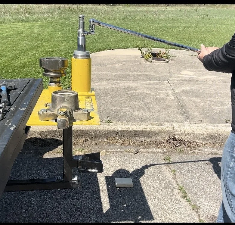
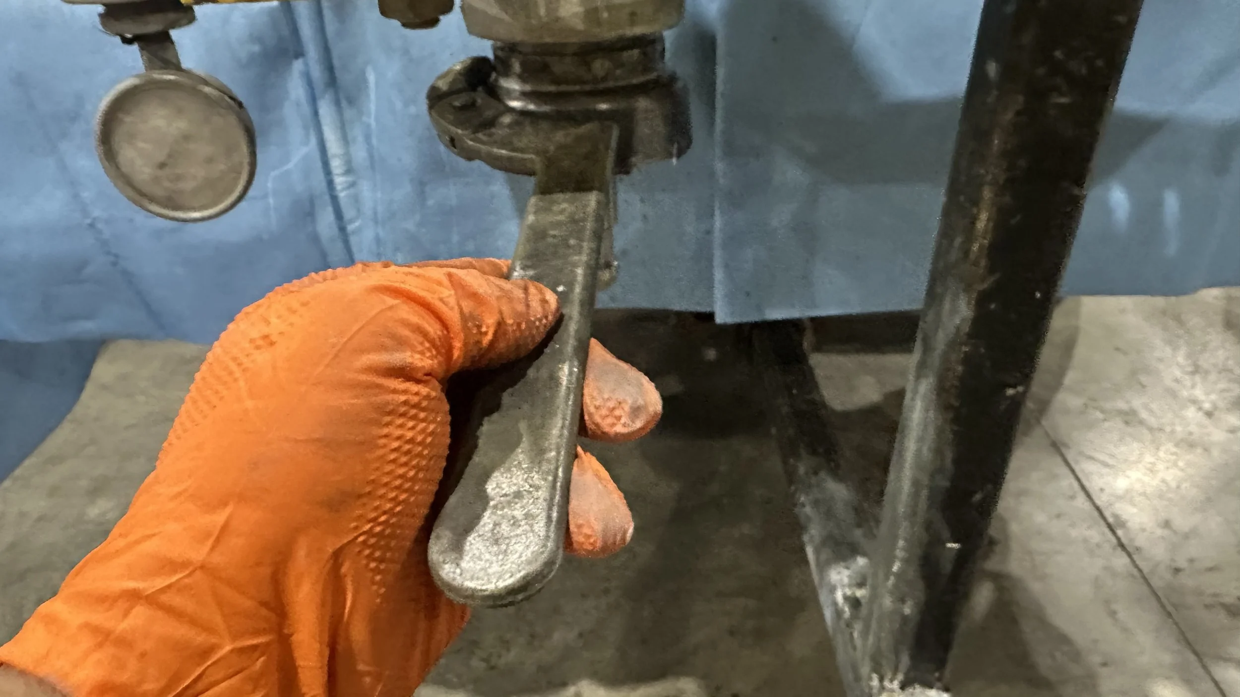
Step6
With a cheater bar and a wrench sized for the top shaft, begin to unscrew lower piston nut counter clockwise. If nut is stubborn it should be extracted to apply some heat and try again. Important to note that every rebuilding requires an extreme amount of cleanliness to avoid any contamination of the threading for the top neck, tie bolts and piston lower. If any debris particularly metal gets into them while rebuilding, will destroy the threading and most likely require the replacment of that piece.
Step7
Once the piston packings have been unscrewed, loosen the set screws on the tower, then pull the piston and cylinder out together. Follow the instructions on the Graco new rebuild kit and install the new packing stack. Make sure to apply anti-seize to the threading. Once the shaft is hand-screwed back on, making sure not to flare out the packings. Once lightly hand-tightened, the piston is lowered with the opposing flats back into the tower and follows the same locking procedure as in the previous step. Note to make sure the cylinder is fully seated over the new packing stack.
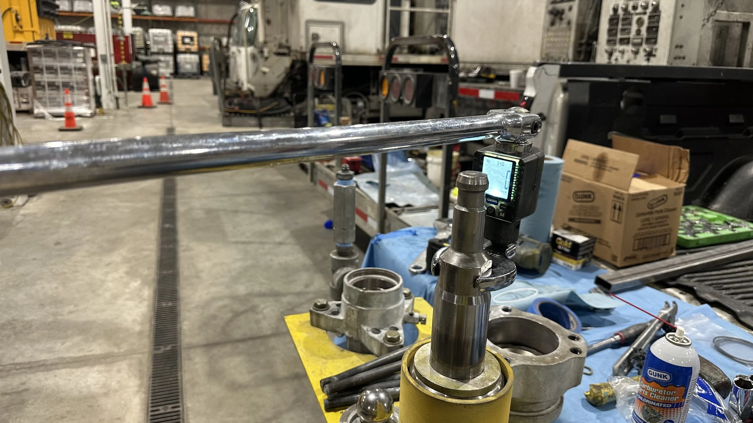
Step8
Having ensured the cylinder is rested well over the packings. A cheater bar which is set up to a torque gauge, the new packings will be torqued to Graco spec of 355 ft/lbs. Picture here shows tools purchased at Harbor Freight. Once proper torque is achieved, undo the tower set screws and pull piston out and leave top centering ring in place. You will notice now that the new packings have been flared out successfully while they are inside the cylinder. Also you will notice the the opposing flats are still protruding past the cylinder which will be addressed in the next step.
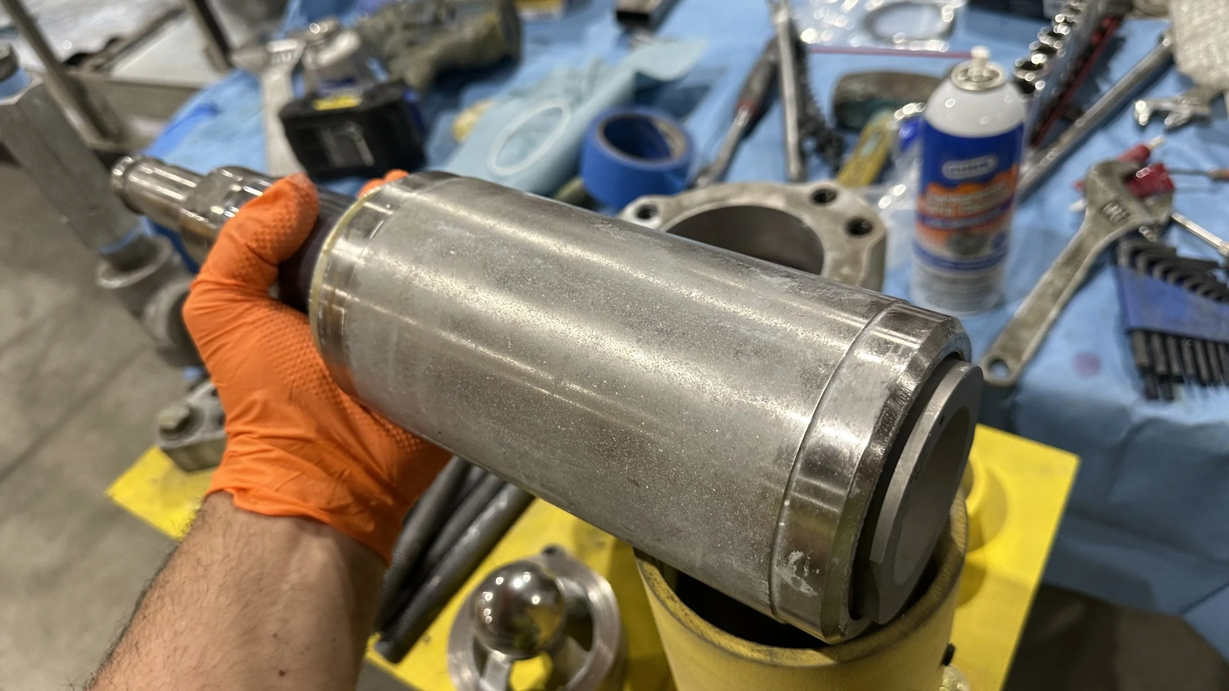
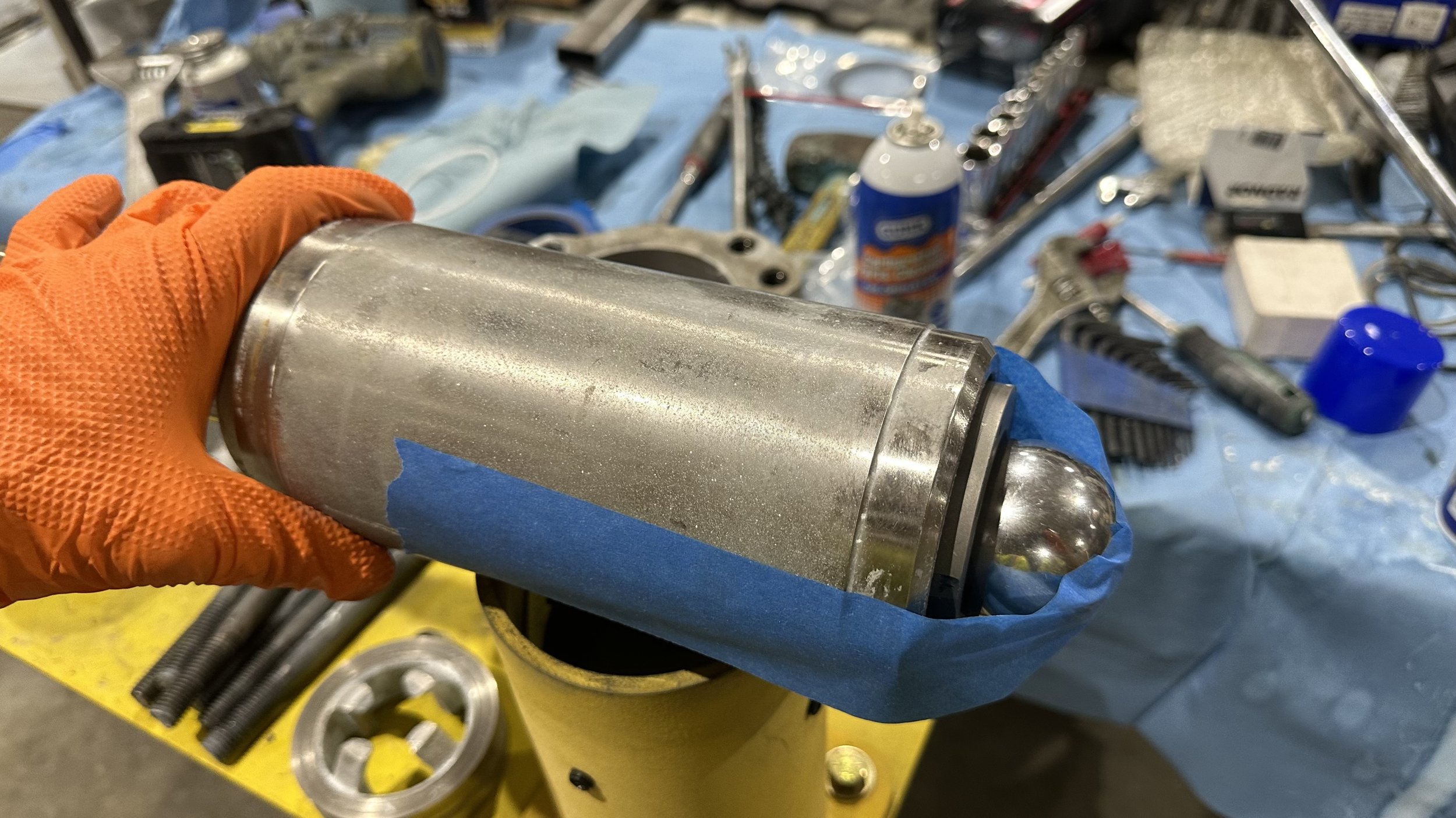
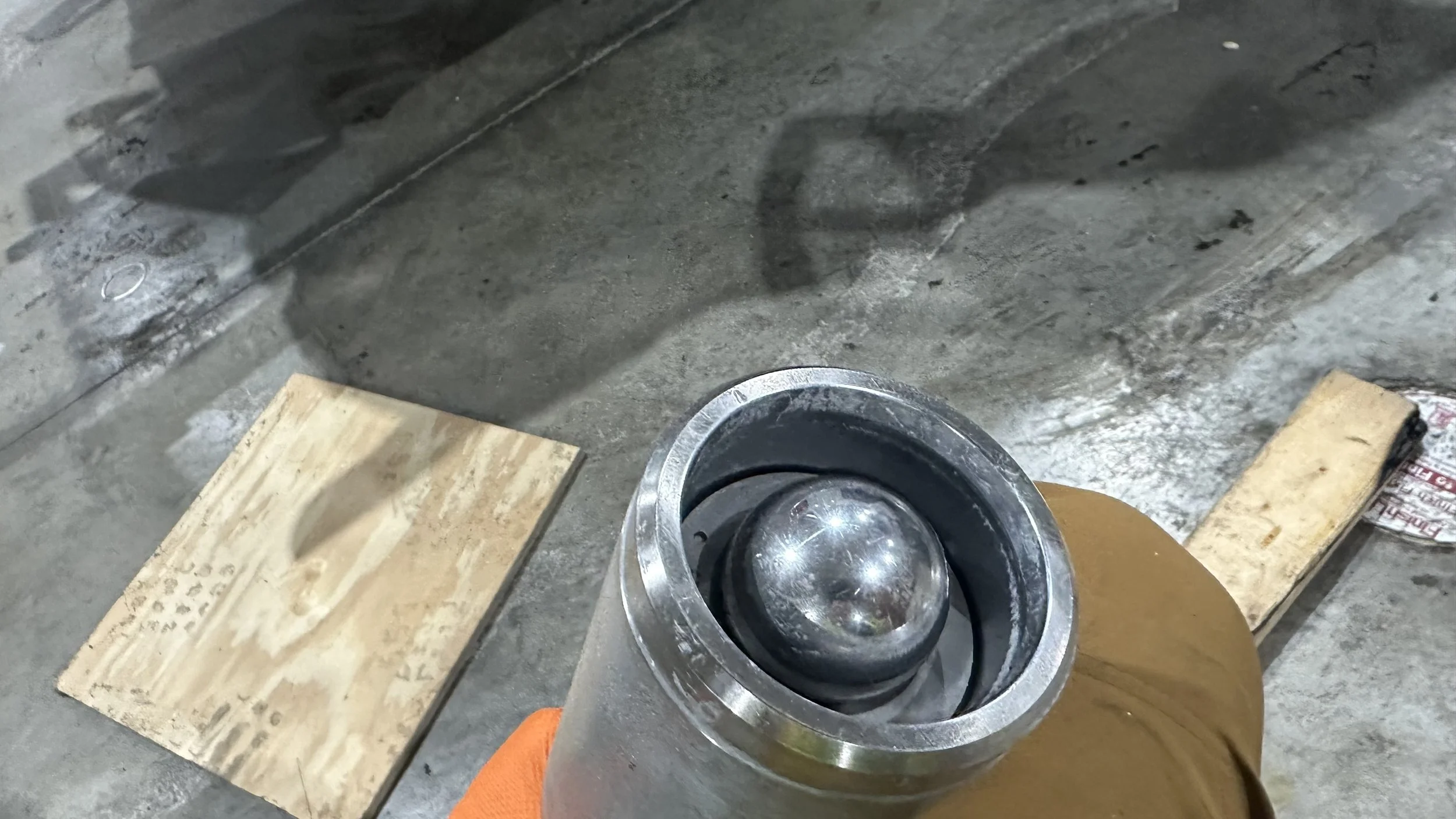
Step9
Since this lip is protruding from the cylinder it will not be able to rest back onto the lower housing of the pump. Using the large ball bearing place the bearing flush with the concaved area of the lower nut and using painters tape to hold it into place. Once in place and still having the top centering ring on top you can grap the shaft and tap the piston onto the 2x4 wooden block back into cylinder until at least the lips are not protruding anymore. Make sure to reset the tape at each moment the ball is floating too loose so as to not cause any damage to the ball or lower nut.
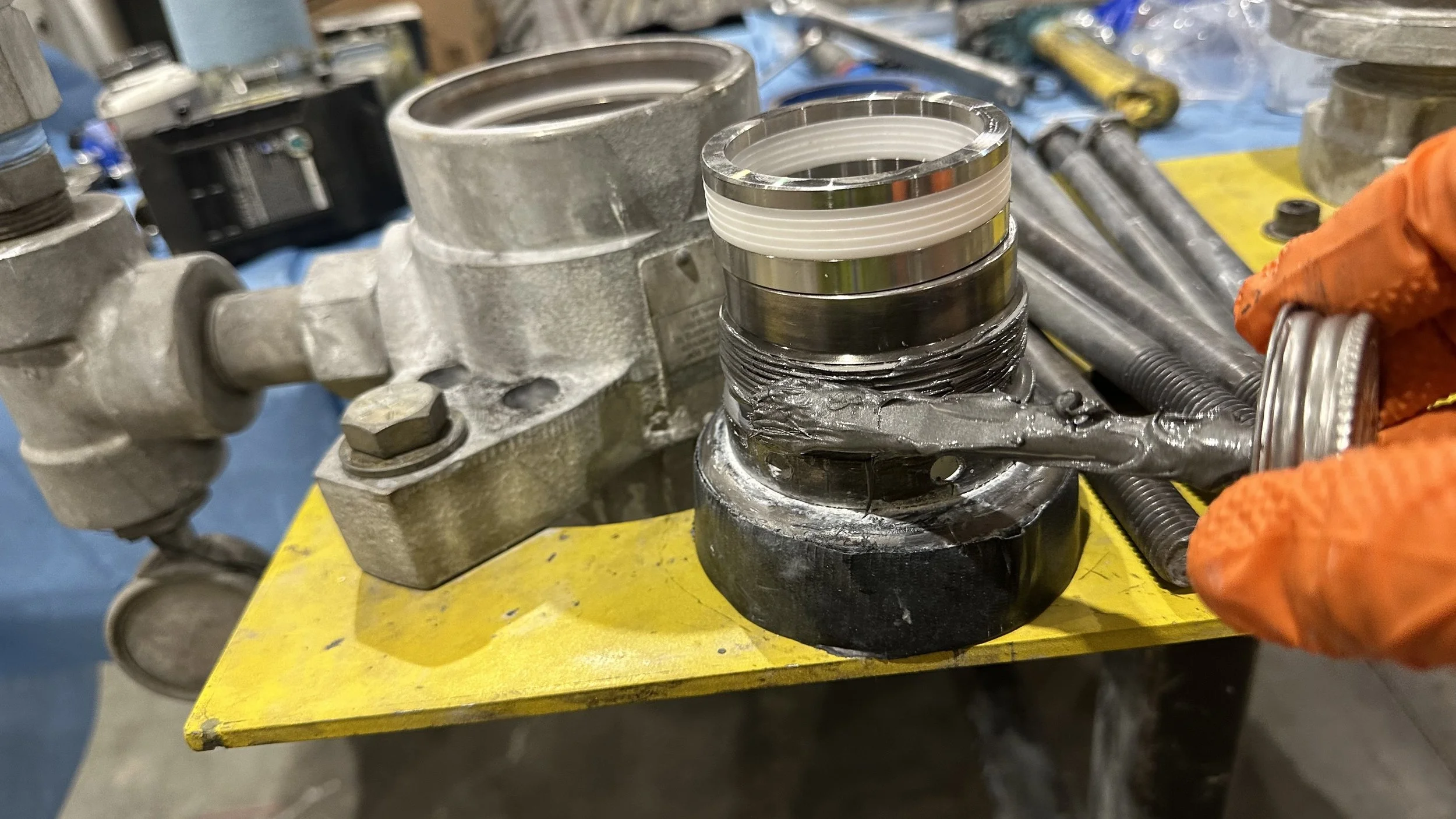
Step10
Using a spanner wrench undo the top packing nut and clean and replace new packings following Graco rebuild kit instructions. Once packings are put together place onto the top packing nut making sure the lips of the packings are facing you. Apply anti-seize to threading and begin to screw back onto the top housing keeping and eye on the packing stack as it is being screwed on until seated well. Make sure not to tighten and flare out the packings as this will make putting the shaft of piston back on very difficult.

Step11
Ensuring the top packings are rested well into place insert the piston shaft and lower until cylinder has seated well over the new cylinder o-ring.
Step12
Once lower housing components have been cleaned, re-assemble using new o-rings. Grab the lower keeping thumbs holding the components in place turn upside down and gently place over cylinder making sure the cylinder o-ring has not shifted. You can turn lower left and right to make sure it is moving smoothly. This is a good sign that the o-ring is seated well. Once ensured it is seated well align the holes and reinstall the 6- 12”tie bolts to a couple threads. At this point apply anti-seize to the threading and then torque bolts to 190 ft/lbs alternating the pattern to make sure the the cylinder o-rings are being evenly compressed.
Step13
After tie bolts have been torqued to Graco specification. The top packing nut can then be torqued using a spanner wrench and cheater bar. This nut gets torqued to 250 ft/lbs.
Need a more stable rebuild setup? See the PumpLocked field rebuild platform.
Step14
This concludes the rebuilding. However, keep in mind that while the pump is locked onto the platform, this is a good time to take off the pump checkvalve and inspect to see if it needs to be rebuilt, then re-install it. Once this is completed now the three bolts holding the pump onto the platform can be removed and the pump taken off of the platform. You have successfully completed the rebuild.